- Product Types of LovejoyProduct Types of Lovejoy
- Couplings & Power Transmission Parts CatalogCouplings & Power Transmission Parts Catalog
- Gear Type CouplingsGear Type Couplings
- SIER-BATH® Gear CouplingsSIER-BATH® Gear Couplings
- Flanged Sleeve Gear CouplingsFlanged Sleeve Gear Couplings
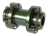
- FSPCR Type (F Type with a Spacer)FSPCR Type (F Type with a Spacer)
- Item Number 69790400177
Item Number 69790400177, FSPCR Type (F Type with a Spacer)
69790400177FSPCR Type (F Type with a Spacer)Lovejoy
FSPCR Type (F Type with a Spacer)
This drop-out spacer design allows for ease of maintenance without disturbing the equipment mountings. It has a lightweight construction to reduce the load on equipment bearings.
The FSPCR Type coupling consists of two standard F Type flex hubs, two standard F Type sleeves, one FSPCR Type spacer and two accessory kits. This coupling is available in either exposed bolts or shrouded bolt design.
Note: BSE = Distance "Between Shaft Ends"
Unit of Measure
Specifications
Description |
N/A FSPCR-2S-SPCR-BSE=5" |
Hub Style |
N/A Shrouded Bolt |
Type |
N/A Spacer |
Hub Material |
N/A AISI 1045 |
Style |
N/A Gear Spacer |
Color |
N/A Metallic |
Coupling Type |
N/A Gear |
Weight |
N/A 13.00 lb |
Complete Coupling Weight (Less Spacer) |
N/A 34.00 lb |
Dimensional Data
Size |
N/A 2 |
Length thru Bore |
N/A 2.440 in61.98 mm |
Overall Length |
N/A 5" Between Shaft End Measurement |
Max. Bore (Dimensions ID1/ID2) |
N/A 2.874 in73 mm |
Dimension AD |
N/A 2.940 in74.68 mm |
Dimension D1 |
N/A 4.750 in120.65 mm |
Dimension D2 |
N/A 4.000 in101.60 mm |
Dimension FD |
N/A 4.000 in101.60 mm |
Dimension G |
N/A 0.060 in1.52 mm |
Dimension S |
N/A Determined by Shaft Separation |
Distance between Shaft Ends (Dimension BSE) |
N/A 5.000 in127.00 mm |
Cubic inches |
N/A 80.00000 in³ |
Performance Data
Nominal Torque |
N/A 31500 in·lb |
Max. Speed (Unbalanced) |
N/A 5000 rpm |
Max. Speed (Balanced) |
N/A 7500.00 rpm |
Max. Angular Misalignment |
N/A 1.50º per Gear Mesh |
Features
Features |
N/A
|
Notes
Notes |
N/A
|


