- Product Types of LovejoyProduct Types of Lovejoy
- Couplings & Power Transmission Parts CatalogCouplings & Power Transmission Parts Catalog
- Gear Type CouplingsGear Type Couplings
- SIER-BATH® Gear CouplingsSIER-BATH® Gear Couplings
- Flanged Sleeve Gear CouplingsFlanged Sleeve Gear Couplings
- FA Type (Alloy Steel) Flex Sleeves (with Seal)FA Type (Alloy Steel) Flex Sleeves (with Seal)
- Item Number 69790403975
Item Number 69790403975, FA Type (Alloy Steel) Flex Sleeves (with Seal)
69790403975FA Type (Alloy Steel) Flex Sleeves (with Seal)Lovejoy
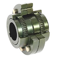
FA Type (Alloy Steel) Flex Sleeves (with Seal)
For use with FA (Alloy Steel) Flex-Flex couplings.
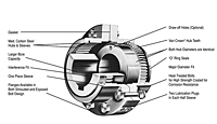
The FA Type coupling provides a higher nominal torque value than standard F Type couplings, and consists of two FA Type flex hubs, two FA Type sleeves (with seals) and one accessory kit. Exposed bolts (E) are the standard design for this coupling, though shrouded bolt (S) designs are available upon request through size 5.5. The FA Type has a max angular misalignment of 3.0 degrees (1.5 degrees per gear mesh).
Unit of Measure
Specifications
Description |
N/A FA-2S-SLEEVE-W/SEAL |
Hub Style |
N/A Shrouded Bolt |
Type |
N/A Sleeves |
Material |
N/A Alloy Steel |
Color |
N/A Metallic |
Style |
N/A Alloy Steel Shrouded Bolt Sleeve |
Application |
N/A Driver and Driven |
Weight |
N/A 6.23 lb |
Complete Coupling Weight |
N/A 34.00 lb |
Dimensional Data
Size |
N/A 2 in |
Max. Bore (Dimensions ID1/ID2) |
N/A 2.874 in73 mm |
Length thru Bore |
N/A 2.440 in61.98 mm |
Distance between Shaft Ends (Dimension BSE) |
N/A 0.13 in3.30 mm |
Dimension AD |
N/A 6.000 in152.40 mm |
Dimension D |
N/A 4.860 in123.44 mm |
Dimension FD |
N/A 7.00 in177.80 mm |
Cubic inches |
N/A 119.56000 in³ |
Performance Data
Max. Speed (Unbalanced) |
N/A 5000 rpm |
Max. Speed (Balanced) |
N/A 7500.00 rpm |
Nominal Torque |
N/A 39000 in·lb |
Max. Angular Misalignment (per Gear Mesh) |
N/A 1.50 º |
Parallel Misalignment |
N/A 0.085 in |
Features
Features |
N/A
|
Notes
Notes |
N/A
|


