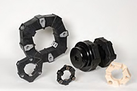
- Product Types of LovejoyProduct Types of Lovejoy
- Couplings & Power Transmission Parts CatalogCouplings & Power Transmission Parts Catalog
- Torsional CouplingsTorsional Couplings
- LF SeriesLF Series
- Item Number 68514476429
Item Number 68514476429, LF Series Flange Hub with Keyway - Inch (Imperial) Bores
68514476429LF Series Flange Hub with Keyway - Inch (Imperial) BoresLovejoy
- The LF Series coupling is designed with a unique and highly versatile elastomeric element. These can be easily integrated into a variety of coupling configurations to meet several application needs. LF Style elements are available in a variety of materials to match the necessary coupling dampening characteristics for tuning the systems critical speed away from the application operating speed.
The element can be connected axially to a flywheel adapter plate or flanged hub and radially to a cylindrical center hub using the appropriate bolts. Axial bolt styles include either socket head bolts with a special dry adhesive, or S-Style bolts, which are similar to dowel pins (seen picture below). The radial bolts are used to connect the element to the cylindrical hub. This unique design is remarkably simple, highly effective and gives the LF torsional coupling unmatched performance capabilities. The coupling selection should be verified with a Torsional Vibration Analysis (TVA) of the system.
Unit of Measure
Specifications
|
Dimensional Data
|
Performance Data
|
Torsional Element Specifications
|
Features
|
Notes
Specifications
Description |
N/A LF4-HUB FLNG-3/4-1/4X1/8 KW |
Type |
N/A Torsional |
Coupling Size |
N/A LF4 |
Weight |
N/A 2.80 lb |
Style |
N/A Flange |
Color |
N/A Metallic |
Bore Type |
N/A Finished Bore |
Dimensional Data
Bore Size |
N/A 3/4 in |
Thread (Dimension T) |
N/A M10 |
Keyway Size (W x D) |
N/A 1/4 x 1/8 in |
Hub Diameter |
N/A 1.770 in45.00 mm |
Length thru Bore |
N/A 1.180 in30.00 mm |
Min. Bore (Dimensions ID1/ID2) |
N/A 0.630 in15.00 mm |
Max. Bore (Dimensions ID1/ID2) |
N/A 1.75 in45 mm |
Dimension FD |
N/A 2.560 in65.02 mm |
Dimension FOD |
N/A 3.940 in |
Cubic inches |
N/A 18.31785 in³ |
Performance Data
Temperature |
N/A -40 to 194 ºF |
Operating Temperature Range |
N/A -40 to 194 ºF |
Nominal Torque |
N/A 440.00 in·lb |
Max. Torque |
N/A 1100.00 in·lb |
Allowable Continuous Vibratory Torque |
N/A 180.00 in·lb |
Max. Speed |
N/A 7000.00 rpm |
Max. Angular Misalignment |
N/A 3.00 º |
Max. Parallel Misalignment |
N/A 0.060 in1.50 mm |
Wind-Up Angle at Nominal Torque |
N/A 5.00 º |
Wind-Up Angle at Max. Torque |
N/A 12.00 º |
Dynamic Torsional Stiffness |
N/A 7500.00 in·lb/rad |
Static Angular Stiffness |
N/A 21.30 in·lb/deg |
Static Axial Stiffness |
N/A 430.00 lb/in |
Static Radial Stiffness |
N/A 2860.00 lb/in |
Shore Hardness |
N/A 60A |
Torsional Element Specifications
Torsional Element Specifications |
N/A
|
Features
Features |
N/A
|
Notes
Notes |
N/A
|


